Wireless Water Feature Meter
Note: Click on (almost) any image on this page to see it full-sized!
Table of Contents:
- The “Why?”
- The End Product
- Bill of Materials
- Beginning of Technical Section
- Source Code
- How It Works
- My Background
- How It Started: The Idea
- Procedure
- The Issues
- Things I Could Have Done Differently
- Thanks
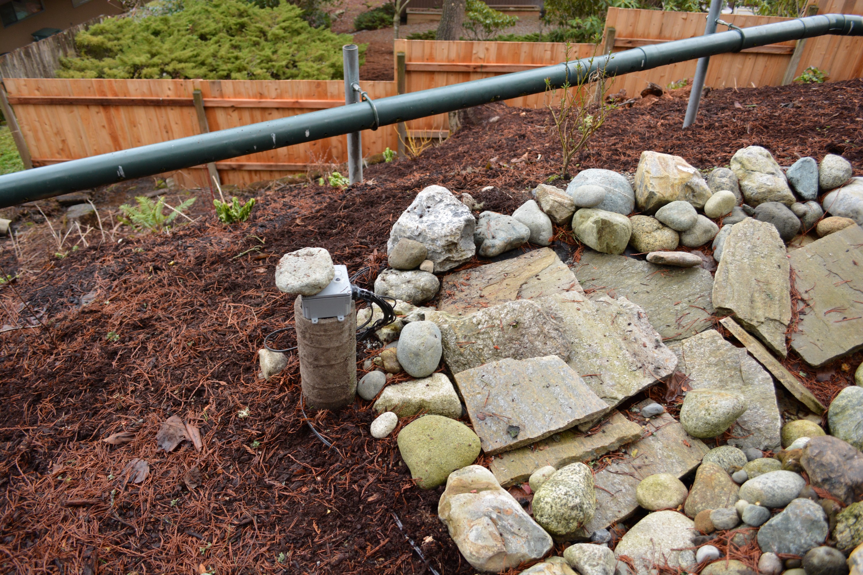
Then, in July of 2013, roughly half a year ago, my parents (mostly my dad) built a running stream in the back of their yard.
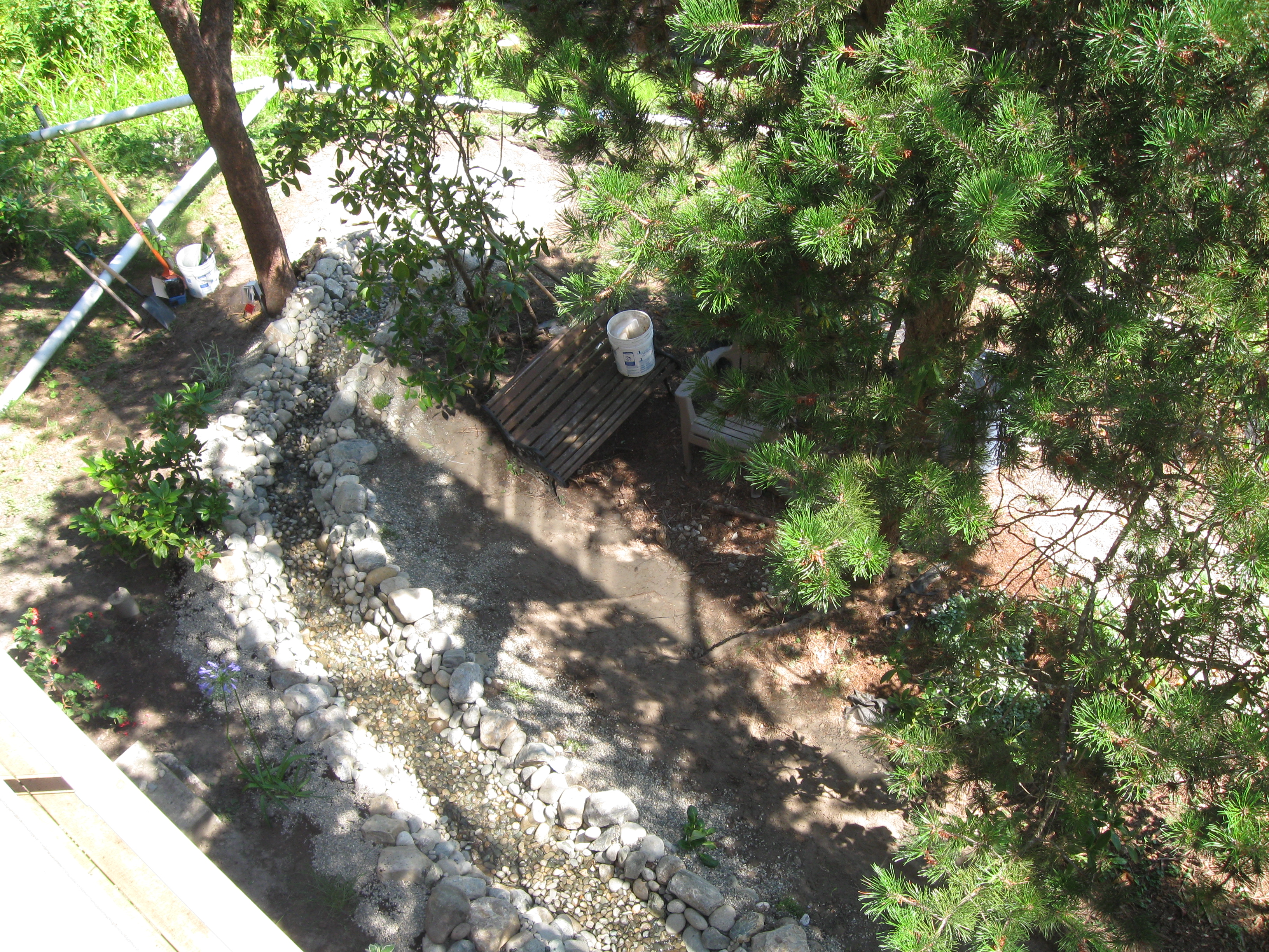 |
| The Stream (from above) |
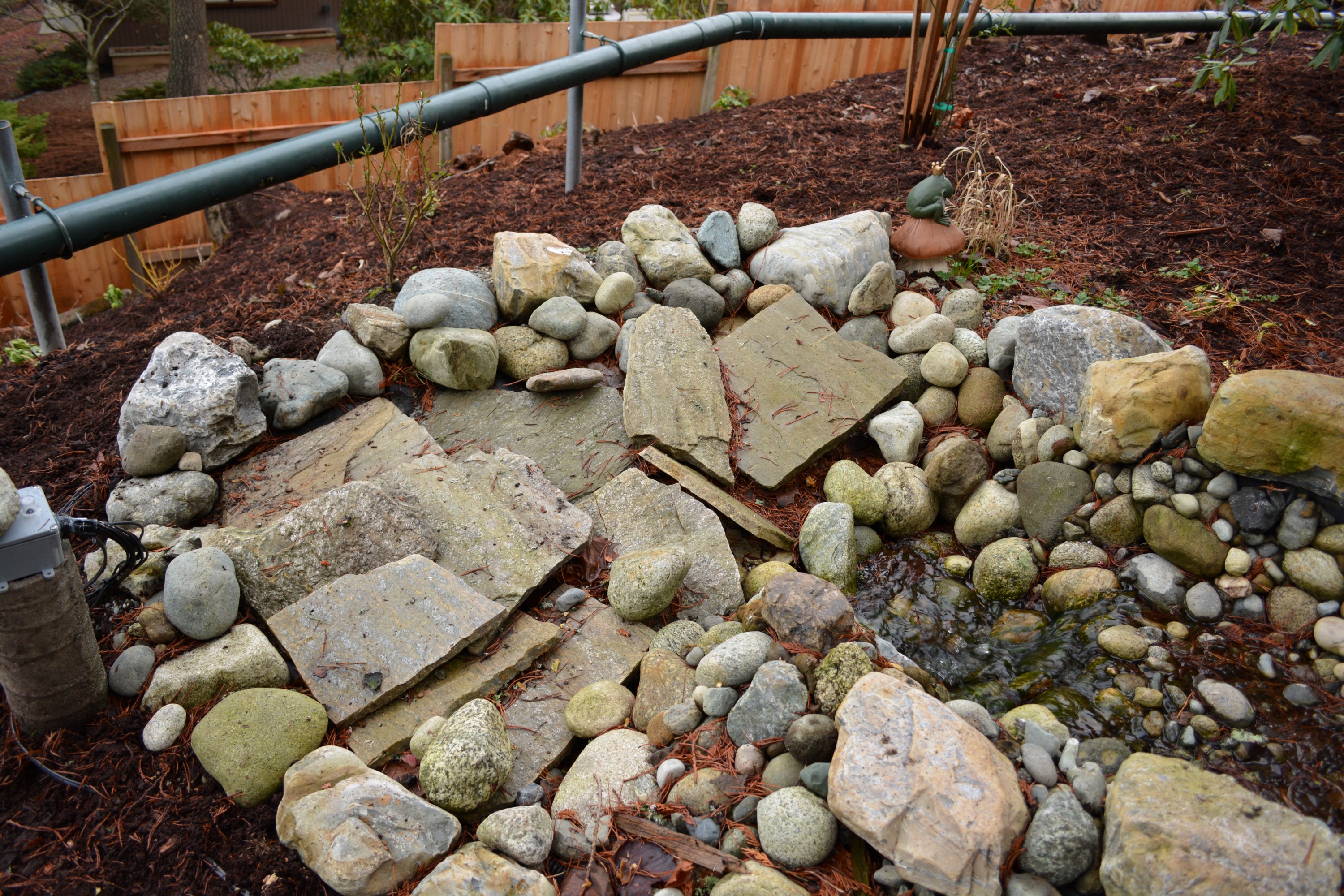 |
| The end of the stream |
Summer classes got in the way of getting work done on the project immediately, so there was some delay, but eventually I started putting time towards it. I first brainstormed different ways I could read the water level of return tank at the bottom of the stream. I did some research online and dismissed many ways that were possible, but I felt weren’t the best. If you want to see my brainstorming and build process more and detail, skip down below to the more technical section, or keep reading and you will get there eventually. Anyways, I eventually landed on the somewhat unique idea of using a long pole with a common anode running the entire length of the pole, with 8 nodes (screws in the pole) that would be connected to 8 analog inputs on an Arduino board.
 |
| A very bad illustration of my idea |
Originally, I just planned to only measure the water level of the stream, wirelessly transmit it from the outside unit to a box sitting inside, and then have the inside box display the water level by way of 8 little LED lights that would either be on or off, depending on the level of the water. However, as I started to design my project, I started to realize that there were more and more features I could easily add with just a few lines of code, and I also found out how incredibly cheap electronics are direct from China using eBay. At a certain point I should have stopped myself and resisted the slippery slope of “feature creep”, but I didn’t, so the end product is way more advanced than I originally planned.
The End Product In terms of the programming that is in the end product, I won’t go into great detail, but will say that I wrote over a thousand lines of C for the program that runs on the microcontroller (if I were to print it out on paper it would use roughly 24 pages) and there are currently no (that’s right, zero) bugs to report.
Time: About 4 days to solder everything and get the enclosures completed, 2 hours to program the external unit, a few days to program the internal unit, and then a few more days to debug all the code. Probably somewhere around 1.5 weeks total of actual work.
What I like about this project, and why I made it, is that there is no commercial product (at least not that I could find) that even comes close to comparison. Most water alarms either use one point of electrical contact to sense whether water is present or not, but not the amount present (such as a buzzer that you might put in your basement to warn of flooding) or something called a “float”, which usually only measure to 2 levels of accuracy – whether the tank is full or near empty. Pretty much all of those commercial products also don’t work wirelessly – the alarm has to be where the water is. Finally, even units that only measure full or empty wirelessly are very expensive – this one is not even wireless, but uses a tethered alarm to alert to a tank being full or empty, but it starts at around 400 dollars .
My end product
- measures how full the tank is in accuracy of 1/8ths (12.5%)
- communicates over 2.4Ghz radio signals (can communicate through walls, has a theoretical range up to 2000 feet, etc.)
- reports outside temperature, outside humidity, and the temperature of the water
- keeps the current time, date, and minutes the system has been running for
- has both an auditory and visible alarm
- has configurable alarm settings and refresh intervals
- Can provide alarms for water level, temperature (for example, if the water temperature is below freezing), and humidity
- What I call “logic checking” – code that makes sure the information it is receiving makes sense
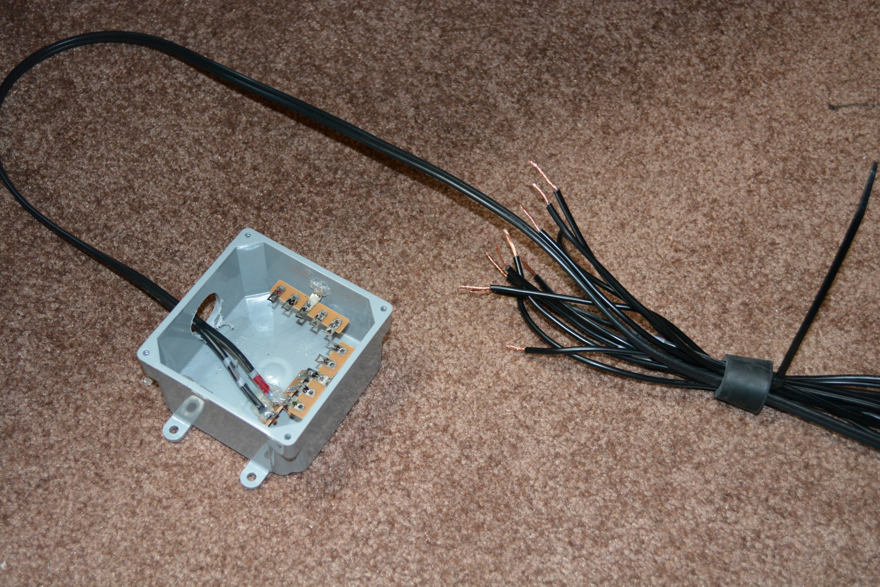
The end product is really two units. One unit is installed outside and should never have to be touched again, and the other unit is a box that sits inside, that has a user interface and displays all the information collected by the outside box. The outside unit is an Iduino Nano (an Arduino clone board), with an ATmega328, stuffed inside a weather-tight enclosure.
 |
| The External Unit |
 |
| The PVC Probe for the External Unit |
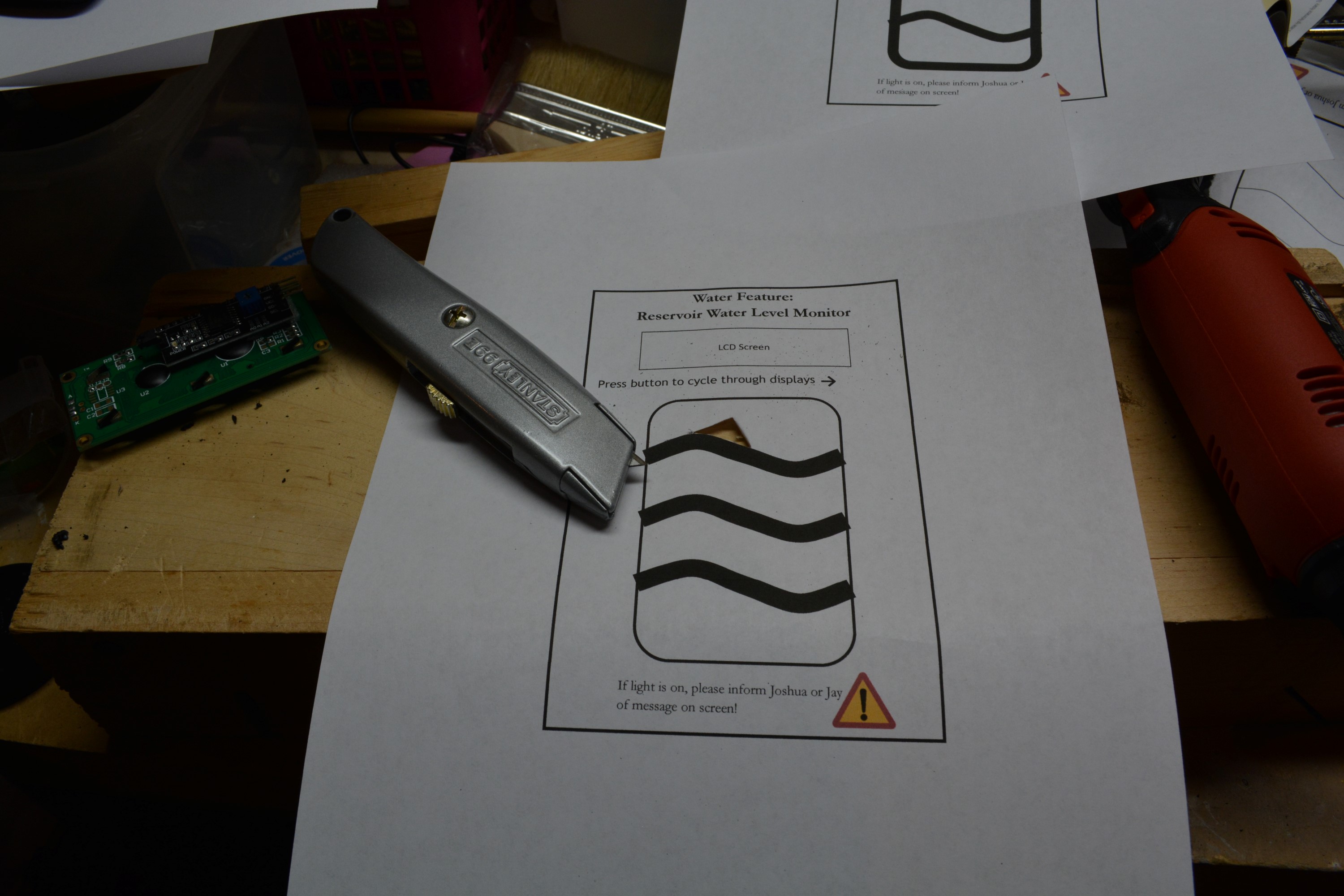
The internal unit is what took most of my time to build and code for, and what the user (my parents) will see at least a few times a day. It is a rather small box, but most of the front surface of it is occupied by an LCD screen, which serves to display all the information about the stream.
 |
| The Internal Unit |
 |
||
| Diagnostics Screen |
 |
| Clock Screen |
- A “weatherproof” electrical junction box, such as this, this, or this. However, I actually am not very satisfied with mine (I believe I have the 6x4).
- An aluminum flat bar for the common anode (I used this one and cut it to match the length of my PVC probe).
- Lots of hookup wire (either 22 or 20 gauge, I recommend solid core, not stranded).
- Arduino Uno (either name brand, or generic SainSmart)
- Cheap auto backup/reverse LCD screen, such as this one that I used
- (2) 2.4Ghz nRF24L01+ RF Transceiver Modules (Amazon, or you can find them much cheaper on eBay, but shipping might take 2-4 weeks)
- Arduino Nano (or clone, such as this one that I used)
- Tools: Soldering iron, solder, desoldering wick, hotglue gun, hotglue, epoxy (for weather sealing), rotary tool for cutting enclosures (I highly recommend this one), wirestripper and wirecutters, wrench, screwdriver
- Components: transistors, multicolored LEDs, LED holders, momentary pushbuttons, sliding switches, perfboard (I used some random boards from RadioShack, but Amazon also sells them), buzzer, 9v battery, various resistors, terminal strips, RCA plug/cable, galvanized bolts and nuts (available at hardware stores), weatherproof PVC pipe (also at hardware stores)
- Special parts: DHT22 (Amazon, or cheaper on eBay), DS18B20 waterproof temperature sensor (Amazon or eBay), Real Time Clock “RTC” module (Amazon, or cheaper on eBay), rubber stopper/plug for creating the seal around the cables going into the external unit (I got mine from Ace Hardware, but most hardware stores should carry them)
- Weatherproof landscape lighting cable (I recommend 16 gauge or thicker – lower numbers are thicker) for the water depth probe and extending the USB power cable for the outside unit (Amazon, HomeDepot, or local hardware store)
- AC-USB Adapter for external unit, AC-DC barrel adapter for inside Arduino UNO unit and to power screen (needs to be 5.5x2.1mm center positive, at least 2 amps to power both UNO and LCD screen, such as this one)
Source Code: As of right now, I have no plans to ever release my source code (either for the internal or external units). There are a few reasons why. First, this was my first programming/electronics project. As such, although my code works, it is messy and I would be embarrassed to have strangers look at it. Second, it would likely be of no help to anyone. I haven’t really provided enough information in this writeup so that someone could actually duplicate my project, and every stream is going to be different, so there is no way someone could duplicate the electronics in my project exactly, to where my code would actually run the same.
How it works: Before covering how I made it, maybe first I should address, in a more technical manner than I did above, how the units work. The inside unit has an LCD screen that displays information about the air and water outside. If the user presses a certain button, or a preset amount of time passes (right now set to 20 minutes), the inside unit will request an update from outside. It does this by sending an integer value over 2.4Ghz using the incredibly cheap nRF24L01+ Radio (can be purchased on eBay for as low as $1 per radio). The outside unit is constantly listening, and when it hears that integer over the radio, it starts to gather data to send back. It quickly supplies 5v to the common anode and then does analog reads of the 8 screws to get the water depth, measure the temperature and humidity of the air inside the enclosure by using a DHT22 sensor, and the temperature of the water by polling a DS18b20 waterproof temperature sensor. It gathers all that data in a matter of milliseconds, packs it into an array, and sends it back to the inside unit, which is now switched to a listening mode and is awaiting the updated information. Upon receiving the new information by way of the radio transmission, the internal unit inside the house rips apart the array and stores its values into variables in memory. It then reports back the values to the user by displaying them on the GUI. If one of the new values is outside of a preset range (that is adjustable), for example, if the water is below freezing, than the alarm LEDs will flash and an alarm buzzer will go off (that unfortunately sounds identical to our dishwashing machine, which means everyone will ignore it).
 |
| A sample error screen |
|
| Clock Screen |
|
||
| Diagnostics Screen |
My Background I’m a 21 year old male, living in Seattle, a full-time student, and a complete coffee addict. Keep in mind, particularly while reading this section, that I am completely new, not just to Arduino, but coding and electronics in general. Prior to this project my only experience with code was a summer camp as a child learning ActionScript (the code that is behind Adobe Flash), a robotics class in Highschool, that didn’t even use code (it used drag and drop blocks, which I actually was able to dig around and figure out it turned into plain C before compiling and sending to the robot), and basic HTML/CSS for some web sites. My only experience with electronics had been taking stuff apart (which I loved to do, sometimes to the horror of my parents as I dismantled electronic gifts and items I had scrimped and saved for) and maybe once or twice soldering super simple wire connections on something that had broken. I have had no classes on C, no classes on even basic circuits (except for maybe a few days in elementary school and a few days in AP Physics), and certainly no experience or education in microcontrollers.
For most people like me, who came to the table with little to no experience with electronics and software, the recommendation is usually to take things slow and use free online courses, video lectures, practice homework, and build-it-yourself kits (such as from RadioShack). You might take a few weeks to learn the basics of C programming, then another week or two to study basic circuits, then another week to combine the two to create some “hello world” programs and flash some LED bulbs. However, those that know me well also know that patience is not a virtue I really have. I was going to have NONE of that. So I didn’t. I knew what I wanted my end product to be, so I just made a mad dash to get to it.
How it Started: The Idea I already outline the rough idea at the beginning of this webpage – to be able to wirelessly check the water level of the outside tank – but how I chose to do that was a hard process. I started by breaking it down into parts; the first idea to tackle was the most difficult; how do I measure the water level? I brainstormed different ideas, as well as did online research, and eventually came up with a list of possibilities, only one of which met my needs. Possibles were:
- A float. These are insanely common in measuring water level and are used just about everywhere. The Keurig pod coffee makers use magnetic floats in their reservoirs to know if there is enough water left to brew another cup, or if the warning light needs to be lit up. You can also buy commercial units with a float attached to an alarm.
- The biggest problem with floats is their lack of accuracy. Most floats act basically as a giant switch – they are either on or off – there is no in-between. Considering how cheap they are, this is absolutely wonderful if you just want to be alerted when the water reaches one specific level that you set, or to have it turn something on, but it is bad if you want more points of accuracy. I believe continuous floats exist, that can output multiple values, but my guess would be that they are primarily for industrial use and probably cost hundreds, if not thousands.
- A waterproof sonar sensor pointed downwards towards the bottom of the tank. The sound should ping back off the surface of the water and the sensor should be able to, very accurately, return the current level of the water. Here is an online example: link.
- Problem: The accuracy of this sensor would be awesome to have. I could probably know the depth of the water down to a few millimeters. However, a truly waterproof one would likely be pricy, and most importantly, since there are rocks covering the top of the tank, and the tank is really a non-uniform hole in the ground, filled with a pump and various floating debris, it would not only be near impossible to mount the sensor in a place where it can echo off the water, but it is highly likely that debris in the water would mess with it and cause it to give back incorrect readings. A great idea for an actual “water tank”, in which water is relatively stagnant, but probably not good for a tank where water is continuously rushing in and out.
- Pressure Differentials: I didn’t do much research here, but what I found made it sound difficult to work with in my scenario, as again, I am not really working with a “tank”, but rather a hole in the ground.
- There are a few interesting ideas on this forum page, but not exactly what I ended up doing. Still useful to look at though.
- Strings of Resistors. This is a very interesting concept that I did not come up with during brainstorming, but found online on a few different sites (link 1, link 2). It is actually a pretty neat way of measuring water – a bunch of resistors are in series, from a power source, to an analog input on the Arduino (also of course, back to ground). As the string dips below the water, the resistors start shorting out to the return path, and the resistance changes – this provides the Arduino with a variable resistance level that is directly correlational to the depth of the water.
- Why didn’t I use it? Well, for one, after coming up with the next idea, this one seemed a bit complicated and convoluted for its purpose. Most importantly though – when electrical current is passed through a metal conductor under water, oxidation takes place, which results in the corrosion of the metal conductor. I could find ways to slow this down, but it would complicate my build further – the idea, without modifications, would likely result in failure in under a year, considering the thickness of the metal wires coming out of most resistors.
- The chosen idea: A basic circuit. There is a flat aluminum stick that runs the entire length of my PVC probe and acts as a common anode, supplying a positive 5v (which is generated by the Arduino) to the tank. Also on the PVC pipe/probe are 8 screws, to which wires are attached. Each of these 8 wires goes to a separate analog input pin on the Arduino outside. If a screw is submerged in water, a circuit is created between the analog pin and the 5v of the common anode, so the analog pin reads a rather high voltage/value There is also a pulldown-resistor circuit connected to each of the analog input pins to reduce electrical noise and ensure that when a screw is not submerged in water, the pin only reads “0”. This was really my first or second idea, but I still did my online research just to confirm that I should go with it. After looking at the alternatives, it is the simplest, cheapest, and can provide me with as many accuracy levels as analog pins I have (I chose to just go with 8), although you could theoretical get even more levels by using digital logic circuits to return various levels to the Arduino depending on the level of the tank. My way works well though, and I didn’t over-engineer.
- What is important to note, since I mentioned it as a negative for another idea, is that when metal is conducting electricity under water, oxidation occurs and the metal will rather quickly corrode. This method is no exception. However, I took several steps to ensure that it will occur at an extremely slow rate, to the point that it will likely fail because of some other component, such as an AC transformer failing, long before the PVC probe ever fails. The first step was to use a thick (1/8” thick) aluminum flat as the common anode to conduct the positive voltage. There were several different types of flats available, and at least according to my research, aluminum was less likely to corrode than the others, at least at my price point. I found the flat at Home Depot, but I know for a fact that Ace Hardware also carries them (as well as probably most hardware stores). For the conductive screws serving as “nodes”, I used galvanized screws as opposed to plain zinc screws – galvanized screws are more expensive and look duller, but they will resist corrosion longer while still conducting electricity. Again, easy to find at almost any hardware store. Finally, for the wires used, I used “low-voltage landscape lighting cable”, which is cheap for really long lengths (I needed about 80 feet), has a copper conductor mixed with other metal strands (great for electrical conductivity), is really thick (typically 16-gauge, great for slowing down corrosion failure), and is covered with a really thick PVC insulation, which means it can actually be buried underground and will survive exposure to harsh weather. I bought 50 feet of it at Home Depot, and then when I ran out of that, I bought another 100 feet at Ace Hardware (of which I used very little). It was much cheaper to buy at Ace, but your experience may differ. Of course, you can also always buy it online with Amazon.
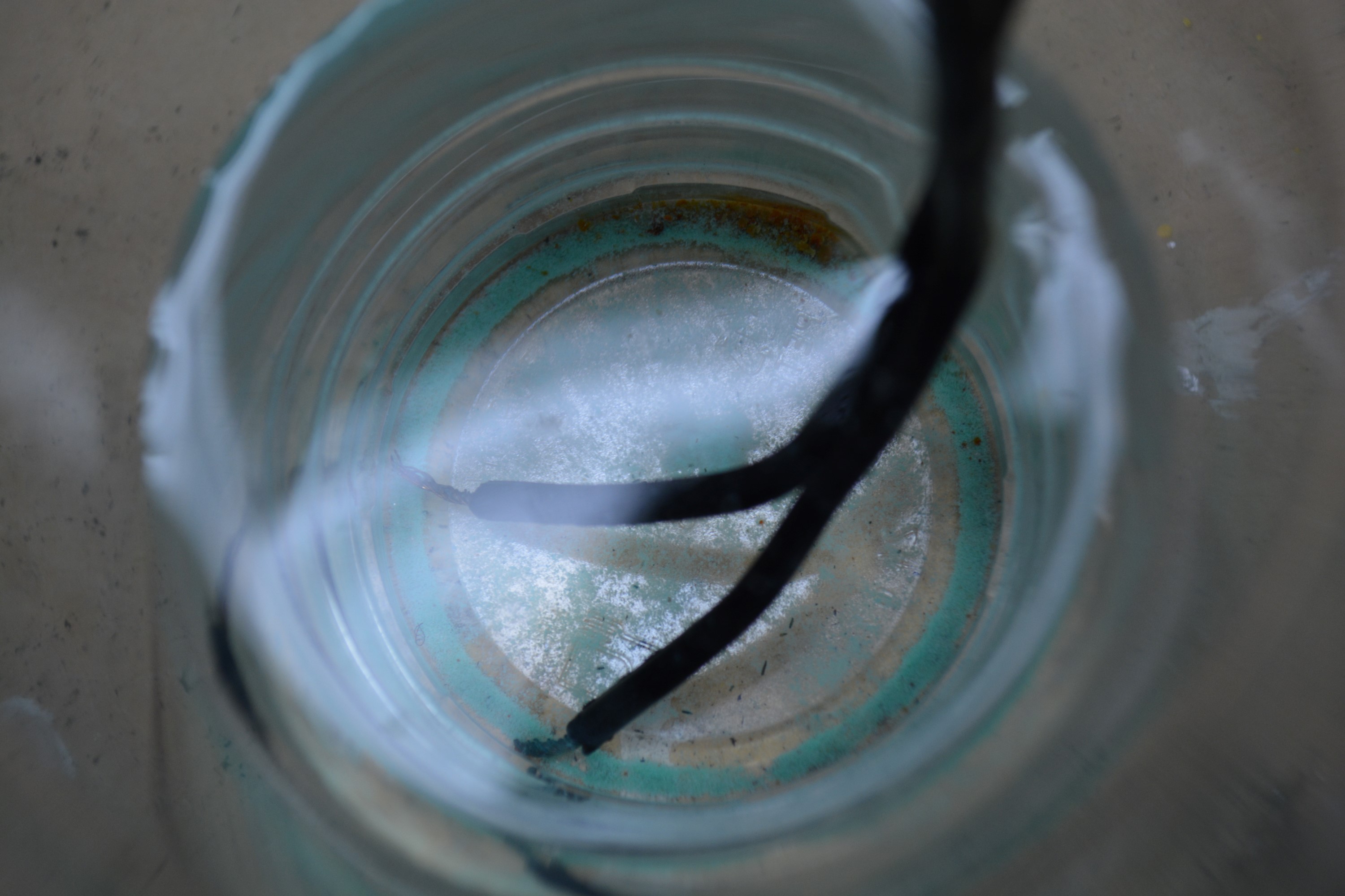 |
| Blue Powder Substance |
 |
| Flashing LED |
After being convinced that my idea would stand the test of time, I thought it best to design the hardware first. At first, I wanted to have the internal unit have individual LEDs, 8 of them in a vertical column, to light up to represent the water level of the outside tank (eg: if it was full to three levels, then light up the bottom 3 LEDs – this instructables is the closest to what I originally had in mind). I quickly discovered a few issues with this plan though, mainly that as I added more sensors and information to my idea (“I SHOULD HAVE IT RECORD HUMIDITY!!! YEAH FOR FEATURE BLOAT!”) I would have to have a small LCD panel to display the information, and then a user would have to press a button multiple times to display whatever page of information they want to see.
 |
| My original idea for display |
Sometime around discovering TVOut I also started acquiring a lot more parts. I visited RadioShack and got transistors, resistors, and other various small components (make sure to ask for a student discount if you have a student ID – an extra 10% off all purchases!), shopped at Home Depot and picked up the copper wire, aluminum flat, and weatherproof enclosures, and finally, started purchasing the bulk of my supplies from either Amazon or eBay, eBay being my preferred retail website for electronic components, as they all are pretty much with free shipping and at a fraction of what I would pay at Amazon. The downside to ordering off eBay is that you are usually ordering directly from distributors or manufacturers in China or elsewhere in Asia, so you can expect anywhere between 1-4 weeks for delivery. It is very hard to go from Amazon Prime to having to wait 3 weeks for a package.
Prototyping Around this time, I was also looking for ways I could organize my ideas about the hardware for the project and experiment with configurations without having to prototype everything out on breadboards. Enter “Frtizing”, one of the coolest programs I have every used. Fritzing is a little hard to describe, but is close to analogous to website wireframing software, such as the Pencil Project – Fritzing allows you to easily create graphical representations of electronic circuits and prototype your ideas and save them.
 |
| Looking at Fritzing on my laptop |
Building Shortly before I did all the soldering work, I cut out parts of the box to go inside the house with a rotary tool. I cut out a section of the front to allow room for the LCD panel (which is really just an unmodified car LCD screen I bought on Amazon, designed to be attached to reversing cameras), holes for LED holders and LEDs, holes for the 5 momentary pushbuttons, a hole for the extra RCA video plug, a hole for a sliding switch, and final two holes for the connectors for the Arduino Uno inside the box, one for the USB connector and the other for the barrel power connector.
 |
| Cutting the Enclosure |
 |
| Messy wires!!! |
After cutting my enclosures and doing the majority of the solder work, I started work on the water probe. I used weather-resistant PVC (I am not sure if that is exactly what it is called, but it is grey and available at most hardware stores. It is stronger than the plain white PVC and has a higher rating.) and cut it to about the height of the water tank at the end of the stream. I then also cut the aluminum flat to the same length as the PVC (I used my Black and Decker rotary tool with a cut off dics to cut the aluminum flat). I cut a hole in the bottom of the pole and secured my DS18b20 waterproof temperature sensor in it, and then cut 8 more holes for the 8 analog sensors. I ran galvanized bolts through the 8 holes, using nuts to secure them, and threaded the ends of my 8 analog wires around the nuts, using mostly tension to hold them in place. I also used two bolts to secure the aluminum flat to the PVC pipe. To understand my design easier, I recommend looking at the pictures.
|
| The PVC Probe for the External Unit |
 |
|
| Starting to attach all the wires to the terminal strips |
 |
| More wires attached! |
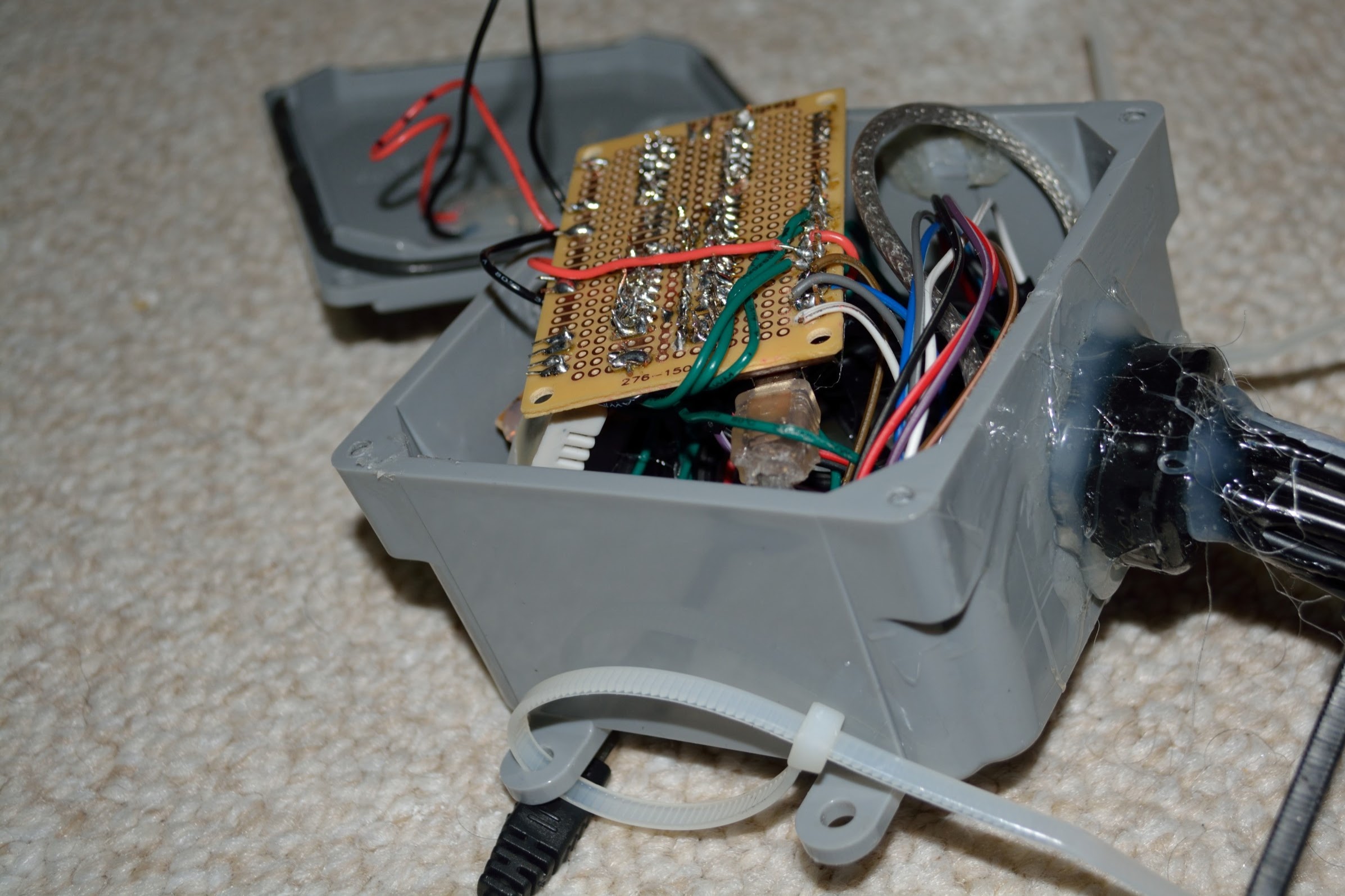 |
| Cables attached, seal expoxied, almost done with external unit! |
Once everything was all wired up, it was time to start work on…
The Programming Like I said before, I have no real programming experience, so take the information I share here with that consideration. That being said, I ended up writing over a thousand lines of codes, which compile without errors, and I currently have no real bugs to report.
I really only used three programs to help my write my code. The first is the official Arduino IDE, which really provides very little in terms of an interface. There is no autocomplete or suggestions for functions, no collapsing of sections, and no debugging. However, it super easy to use, since it just requires one click to compile and upload to your Arduino board, and it is lightweight, so you can code without distractions. I would highly recommend starting out with the official Arduino IDE if you are new to programming, as its lack of features actually make it better for a beginner; there is let to get confused about and its limitations force you to learn and understand the code you are producing. If you are an experienced programmer, you can use pretty much any IDE you care to use (the most popular usually being Eclipse). I haven’t really gotten into alternative IDEs yet, but I have a feeling I might at some point, as Atmel Studio looks especially promising, considering there are ways to debug and use breakpoints with it.
Another piece of software I used was Paint.net. If you know what Photoshop is and what Microsoft Paint is, think of Paint.net as a happy medium between them. It is way more advanced than Microsoft Paint, and offers things like cloning, layers, transparency, and more, but stops short of the more advanced features of Photoshop. By not being quite as advanced as Photoshop, it is able to maintain a very small installation (currently uses a 3.5 MB installer), and it runs blazing fast even on the slowest of computers. Normally you would never need something like this for an Arduino or electronics project, but to prototype what my GUI would look like on the LCD screen using the TVout library, I needed a program I could use very easily and quickly to manipulate images on a pixel-by-pixel level. Paint.net allowed me to do just that and was integral in allowing me to create different GUI designs and even an animation.
Finally, I used one of my all time favorite programs, and it has been one of my favorites since long before I started work on this project, Notepad++. Sorry to keep using comparisons, but if you are familiar with Microsoft Notepad and Microsoft Visual Studio or Eclipse (or even Microsoft Word), Notepad++ is a somewhere in-between. It has the minimalist design of notepad and the small footprint and fast runtime, but it also has many of the features that make a full-fledged IDE so great, such as syntax highlighting and collapsing of sections, spellcheck (by way of a free plugin), auto-completion (available, not forced), multi-tabbed to switch between documents, a document map, zooming, and many more features. What I liked to do was to work on my Arduino sketches (.ino files) in the Arduino IDE, but also have them open in Notepad++. Then, if I wanted to navigate my code once it was really long, it was easier to use Notepad++ to examine it in great detail and look for bugs.
Using these three software programs, I was able to create two Arduino programs (sketches), one that runs on the unit outside, and the other that runs on the inside unit and displays the user interface. It took over a thousand lines of code, many hours of debugging, and many cups of coffee, but in the end the units work amazing and perform much better than I ever expected them to. They have been running for days now without any software bugs popping up, and my hope is that they will continue to run for quite some time. However, the path to this point was not as easy it might sound right now. That is because I have not yet discussed…
- The first issue I ran into was that my LCD screen flickered and was making weird patterns. Not only that, but the entire program was acting strange and values were being reported and sent at values outside of what they should have been. Sometimes the board would just crash and nothing would work.
- The fix: This was a memory issue, one that I would have been more aware of to start with if I had experience with microcontrollers. Turns out, the Arduino Uno, the board I was using, only has 2 kilobytes of SRAM, which is insanely small to today’s standards, or even to yesterday’s standards, considering that the original Gameboy released in 1989 had 4 times that amount of both general SRAM and dedicated to video. When I started writing my code and using the Arduino TVOut library I followed their suggestion and used a default resolution of 128x96. Can anyone see a problem with this? I should have. If you think about it for a second, since the TVout library outputs only black or white, which can be really thought of as a binary value, it would have to create a frame buffer of 128x96 pixels, with each pixel occupying a single bit of memory. If you use simple math and multiply 128 by 96, you get 12,288, which is how many bits of SRAM the code needs (1.5 kilobytes), just to display anything on the screen. Considering that 2kB is only equal to 16384 bits, using a resolution of 128x96 was leaving me with only 4,096 bits of SRAM, or half a kilobyte, to work with. Throw in some more code and the fact that I was using the TVout library to load an entire bitmap image into memory as a bootscreen, and it was no surprise that I was maxing out my memory and inducing a buffer overflow. By reducing my resolution to 120x54, I started using only 6,480 bits for the framebuffer, cutting my SRAM usage roughly in half. This was a huge amount of saved memory and I have had plenty of room for my bitmap bootscreen, all my large variables and arrays, and all the graphic elements.
- The flickering / buffer overflow returned once more, when I completely removed delays that limited the speed at which my program ran. My guess is that if it runs too quickly, something happens with the TVOut library and how it generates frames and uses SRAM. I found that a TV.delay(10), which is 10 milliseconds, is enough to stop the SRAM from getting chewed up and short enough to not impact any functionality of the devices.
- I couldn’t seem to get the TVout library to completely fill the LCD screen.
- When I had to reduce the active resolution of my project to save SRAM I inadvertently solved my problem. I just sat there and played around with different low resolutions until I found one that occupied very little SRAM but also filled most of my screen. That ended up being 120x54. Keep in mind, if you are playing around with values, that the horizontal resolution (in this case 120 pixels wide) has to be evenly divisible by 8.
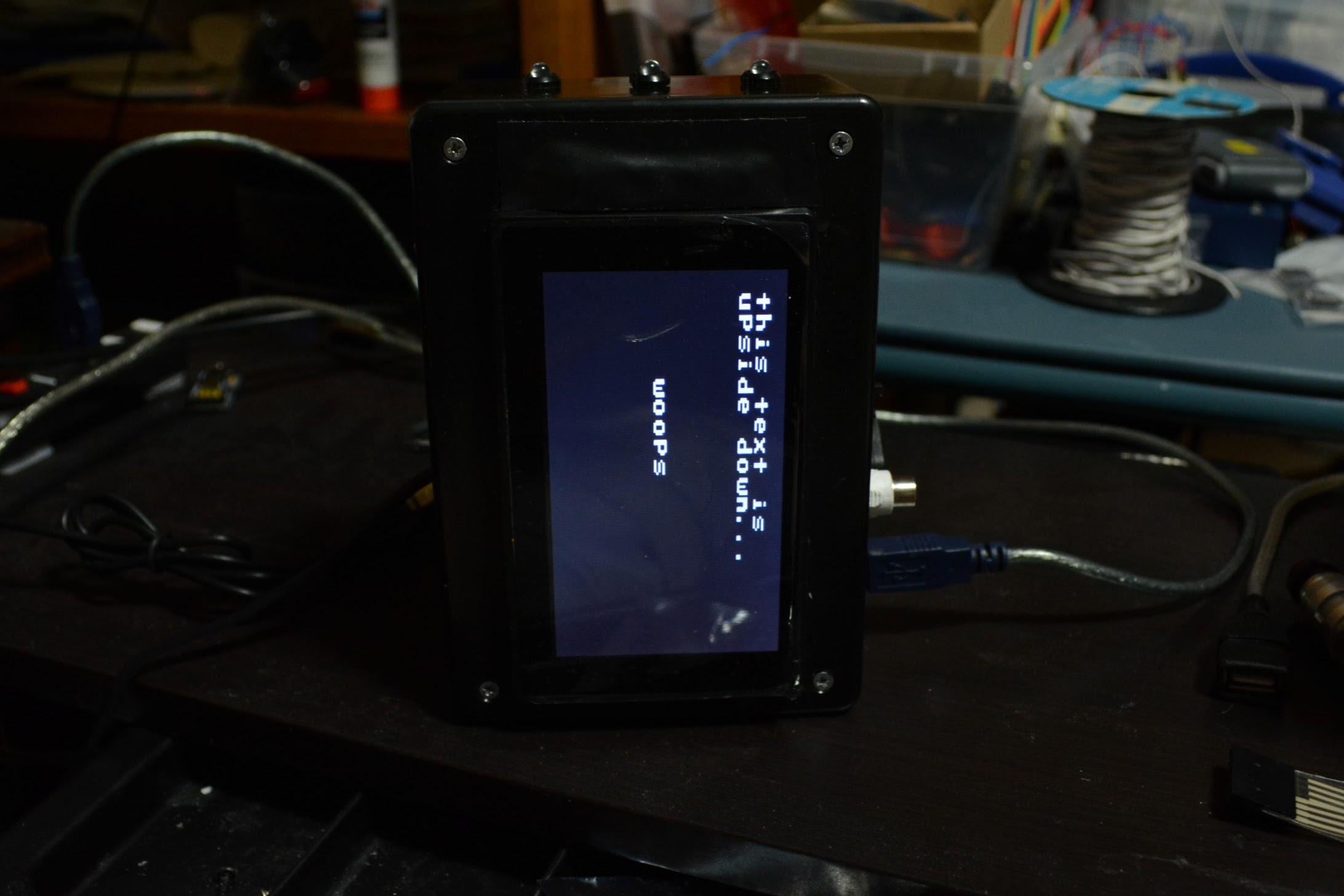
- Everything was sideways!!! The TVOut library is designed to output text and graphics to a screen that is in a landscape orientation, like all TVs are and computer screens – this means that the screen is wider than it is tall. However, because I’m a dolt and didn’t check any of this out before soldering all my connections, cutting my enclosure, and gluing everything permanently in place, my screen ended up being in portrait orientation, which mean that using the TVout library without any modifications resulted in text being drawn sideways (if you were to tilt your head 90 degrees clockwise it would become readable, see the below pictures).
-

Really sideways, not upside down 
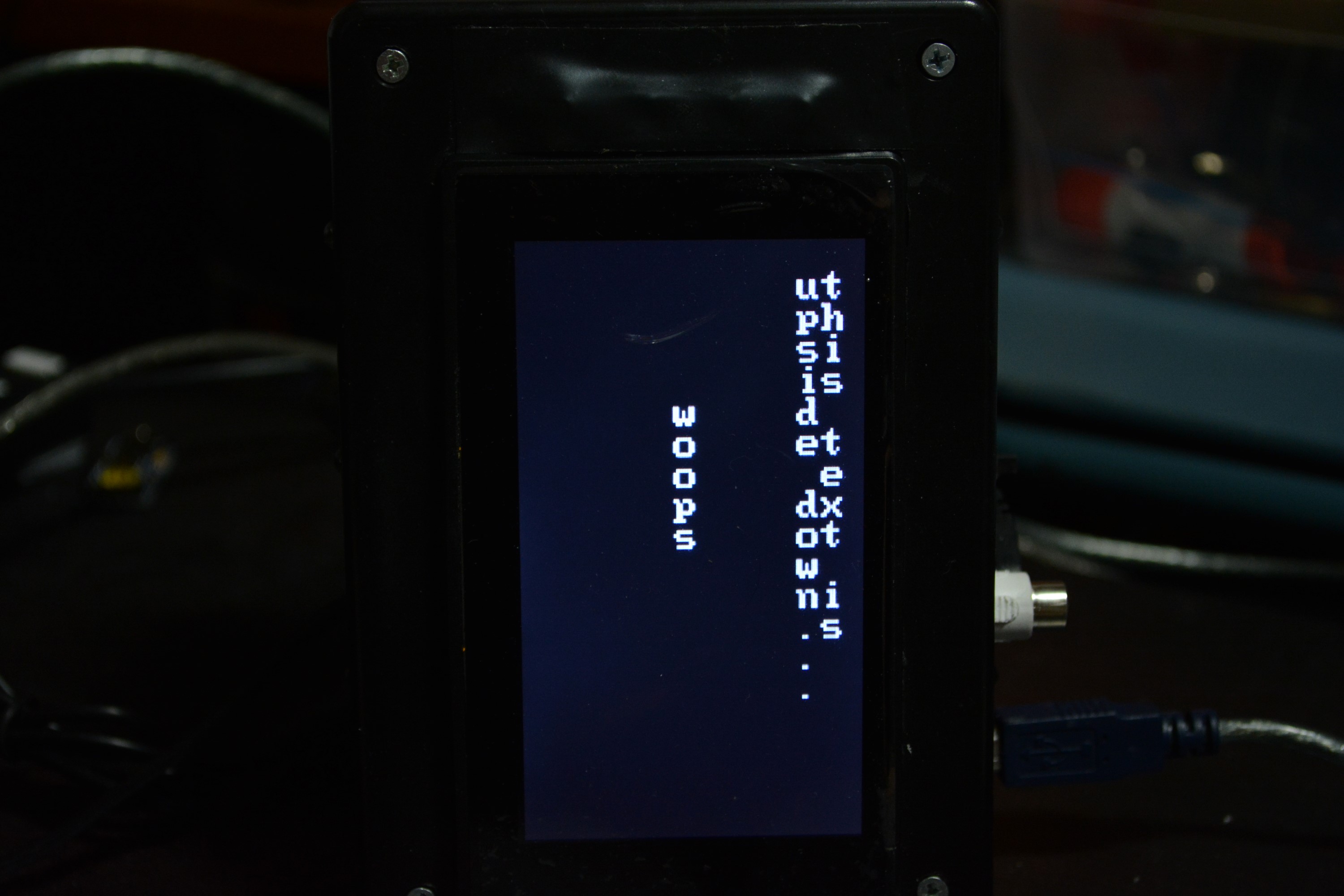
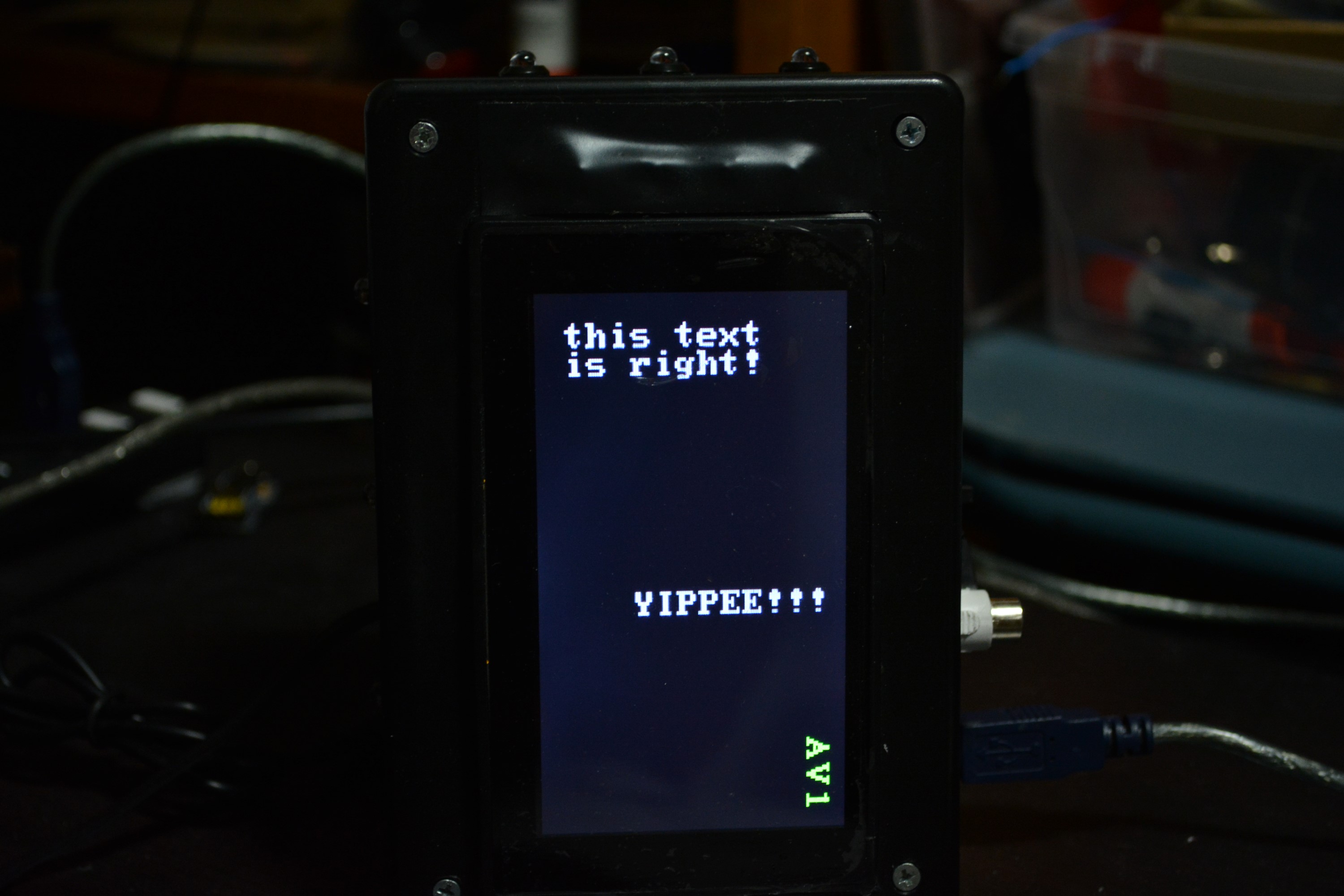
Now the letters are correct, but it is writing them sideways -

Success!!! YES!!! - The easiest solution would have also been the hardest. If I had more experience before starting this project, I’m sure I could have dug around in the library, found where it creates the frame buffer, and then modified the library to generate a buffer that was rotated 90 degrees counter-clockwise. Then I could have used all the TVOut functions as normal and it would have drawn the screen just as how I wanted it to. Instead, I did things the difficult way. First, I actually made my own font. Well, not quite true. I took the 6x8 font that they provided and rotated every character 90 degrees counter clockwise. My dad helped me out by writing a tiny Python script that rotated the binary chunks, or else I would have had to do it by hand (which I actually did for a different font). This still doesn’t fix the problem, as it would now write each character in the correct orientation, but would write the words in the wrong orientation. See the above pictures for a better look. The solution than become more convoluted – to write words on the screen and have them show up readable, I had to individually print out each character at different pixel locations, sort of like if every time you wanted to type on your computer you had to use your mouse to set the cursor in a different place (for every freakin’ character!).
-

Printing "Sending", by printing each character individually - This also made printing numbers very difficult, because I had to write snippets of code to parse variables, find out of a variable was holding a single, double, or triple digit number, and then parse it into different place values depending on its length, and then draw each place value in a different pixel location
- The LCD screen could not be powered off the 5v pin from the Arduino.
- This isn’t really a bug, and it makes sense. The LCD screen is bright and obviously needs a decent amount of power. Although 5v is enough voltage, current is what really matters, and an Arduino board only receiving a few hundred milliamps cannot source enough amps to power the LCD screen. To fix this, you can either solder connections from the VCC on the USB connector before it hits the regulator, or you can do as I did, and solder wires to the barrel connector on the UNO and solder the other ends to the power supply for the LCD screen. I then started using a 2 amp AC-DC adapter with the barrel connector, to ensure that both the board and the screen received enough current. It worked after that.
- When I got to coding for the nRF24L01+ radios, I couldn’t get anything to work. I even tried a program that I had successfully used before with slightly different hardware, and it still didn’t work.
- This was an annoying one. I spent hours checking my code, then a few more hours tracing every circuit on my PCBs with a multimeter and then even more time just trying and retrying to get them to work. Eventually I resorted to purchasing another Arduino to test with, so I could at least see which of the two units was not using the radio correctly. Once it arrived, I tested and discovered that the external unit was not responding to any messages. I traced its connections again and resoldered some connections, but it still didn’t work. Finally, I realized that this might actually not be my fault, and I swapped out the nRF24L01+ radio on that unit with an extra I had lying around (I said they were cheap), and all of a sudden, the exact same code that wasn’t working days ago, was working just fine. Turns out, when you pay a dollar for something that competitors charge roughly 20 for, you are bound to get a dud once in a while. It really was just a bad radio unit. I never really did any further testing to see why that particular radio stopped working, nor do I really care to find out since I purchased two new ones to replenish my supply for less than a cup of coffee. Luckily, instead of soldering the radio directly to the board, I had soldered jumper cables with female ends onto the board and then just placed the pins of the radio into the female ends. This meant that to replace the radio I didn’t have to desolder anything, I just had to pull the pins out of jumper cables and then slide the jumper cables over the pins of the new radio. What I really want to emphasize though, through telling this experience, is that sometimes things are really just broken and it is not your fault, so don’t just look at your own work, look at every part of the puzzle.
- Sometimes the Arduino IDE will not recognize that a new library has been added and linked to your code, unless you do "Import library...", under the "Sketch" option on the top menu bar
- I’m not sure if this has been addressed somewhere online, but it is just a strange, once in every 200 times, bug I have encountered.
- Another nRF24L01+ radio issue: radio.read gets nothing. At one point, I was trying to figure out why using the radio.read function out of the nRF24L01+ radio library was getting stuck and returning nothing, when it should have been returning a payload that the outside unit was sending.
- The documentation for the library says to call “startListening” before attempting a radio read. I did that, however what I found out is that if it is called multiple times, in rapid succession (such as during a while or for loop that is true), it will actually interfere with the radio.read and you will get nothing read. My guess is that “startListening” actually changes something on a hardware level on the radio and there needs to be some sort of delay between the hardware change and the radio attempting a read. Making sure that “startListening” was only called once and not repetitively/rapidly, fixed my problem.
- After changing the datarate of the nRF24L01+ radios, nothing would work!
- The documentation for the nRF24L01+ says that if you need a longer distance range between two radios, you can decrease the data rate of the transmissions. I did this by using “radio.setDataRate(RF24_250KBPS);”, but after doing so, nothing would work. I figured out, and I am not sure if this is addressed in the documentation, that you cannot set the data rate of the radio before using “radio.begin”. This should be kind of intuitive as to why, but I missed it the first time around, so worth warning about.
- My biggest and most challenging issue to debug and fix: random lockup every 60 minutes. This was such a strange bug; every 60 minutes, pretty much on the dot, the GUI screen would freeze and say it had been 29 minutes since last updated (at that time, my code was set with 30 minute intervals between reads) and it would stay that way indefinitely. Even stranger, none of the buttons on the box responded to presses, even though there was no while or for loops that could cause their keypresses not to be read. The board couldn’t have actually crashed, or else nothing would be on the screen; for there to be an image on the screen, the TVOut library has to be actively functioning.
- I initially thought this was a timing issue, since it was occurring every 60 minutes like clockwork. I tried changing the interval between reads from 30 minutes to 20 minutes, but then it just started failing every 3 read instead of every 2nd. Obviously, this was not the issue.
- I next jumped to low RAM as a possibility. As I mentioned before, the SRAM of the Arduino UNO is extremely limited and it has caused trouble before. However, I was able to determine that this was not the case, as it had plenty of free SRAM.
- Finally, I remembered that the TVOut library is insanely dependent on interrupts. This is why you cannot use serial at the same time as using TVOut. I started looking through the different libraries I was using and discovered that the library used by the Real Time Clock and the Wire library (which is necessary to talk to the RTC) also used interrupts. I didn’t want to completely stop using the library, so what I did was move the reading of the RTC out of the very fast looping main loop and into a subroutine, that is only ran once a user presses a button to display the current calendar date and time. Since I could no longer check unixtime using the RTC in the main loop, I replaced my uses of unixtime with TV.millis, which returns the number of milliseconds since the board has started running. Unfortunately, TVOut’s dependency on interrupts also screws with the boards timing, and so the TV.millis returns a rather inaccurate number. I was able to compensate by finding a factor I could multiple the number by to get a more accurate representation of the number of milliseconds the board has been running. Anyways, moving the reads of the RTC and the Wire.begin outside of the main loop fixed the problem. It has now been running for multiple days on end and has not frozen up once.
- There is one issue that I am sad to say has not yet quite been resolved: humidity. As you should be able to see from the pictures, I build the external enclosure in a sealed electrical box from HomeDepot. It has a gasket that runs between the lid and the box, and I screwed the lid on tight enough to seal it. However, every day, since I first plugged it in outside, the humidity has been steadily going up on the readings on the inside unit. It started somewhere around 40 I think, and after about a week and half, had reading 90%. I freaked out, as the alarm kept going off and I had to keep raising the alert level so the high humidity wouldn’t trigger it, but most importantly, I was worried that the high humidity might damage the Arduino board (I’ll remind you that the humidity is measured from inside the enclosure, not the air outside). I live in Seattle Washington, so one fact that I cannot change is that it is very damp here and we get frequent rain (especially right now, when I am having the humidity issue). My current temporary fix was to go outside, put the entire enclosure in a ziplock bag with a bunch of silica gel packets (that absorb moisture in the air), then seal the bag with rubber bands, then cover the bag and the enclosure with saran wrap, and then secure the saran wrap with more rubber bands. After doing that, the humidity readings stabilized, and then dropped a few percentages, but they are still way too high, hovering around 90%. Once it stops raining (which might take a while here), I’ll unwrap it, maybe let it dry in the sun or take a blow drier out on low heat, and add some new silica gel packs and a better seal.
- Instead of using the TVOut library, I could have used an LCD that was designed to be used with Arduino (such as one mounted on a shield), however, those use more pins and I am actually glad I went with TVOut since I learned more using it
- I could have used a different Arduino with more RAM, such as the MEGA, or I could have used a completely different kind of microcontroller platform, such as the Teensy board, which actually has a much more powerful 32 bit ARM processor for about the same price, or I could have gone with a Raspberry Pi. Using a more powerful board would have meant I could have used a higher resolution with the TVOut library, as well as store more information in RAM. As it is, I actually really look how the display looks with the low resolution setting, as it has a nice retro feel and is easily visible from far away. For future projects I might try different boards, but I am glad I went with the UNO for the internal unit.
Finally, I want to say thanks to my parents for raising me and encouraging me to do stuff like this, and especially my dad for sparking the original idea, helping me debug a few things, and letting me use his tools and workroom.